Image Fusion
Image fusion is the process of putting together images from different sources with different input qualities so that you can learn something better. It is possible to improve the quality of previously poor images using the image fusion process, particularly in no-reference image quality enhancement techniques. The image that had been damaged was the only thing used to make the inputs and weight measures for the fusion-based strategy. Four-weight maps can make it easier to see things far away when the medium makes it hard to see them because it scatters and absorbs light. Two inputs show how the colours and contrast of the original underwater image or frame have been changed. These are used to get around the things that can’t be done underwater. To use a single image, you don’t need any special tools, to be underwater, or to know how the scene is put together. The Fusion framework helps keep frames in sync with each other in terms of time by keeping edges and reducing noise levels. Real-time applications can now use better images and videos with less noise, better ways to show dark areas, higher global contrast, and better edges and fine details. These changes can also help applications that work in real-time.
Why Image Fusion
The field of multi-sensor data fusion has evolved to the point where it requires more general and formal solutions for various application scenarios. When it comes to image processing, there are times when you need an image that contains a great deal of spatial information as well as a great deal of spectral information. Knowing this is essential for work involving remote sensing. However, the instruments cannot provide this information because of how they were constructed or utilised. Data fusion is one approach that can be taken to address this issue.
Benefits of Image Fusion
Image fusion has several advantages in image processing applications, some of which are listed below.
- High accuracy
- High Reliability
- Fast acquisition of information
- Cost-effective.
There is a significant difference between the atmosphere above and outside the water and the atmosphere above and below the water. The colours blue and green predominate in the majority of the photographs that are produced by underwater photography. It isn’t easy to see things underwater due to the physical characteristics of the environment, for example. Because light is attenuated when it passes through water, images captured while underwater is not as crisp. As the distance and depth increase, the light becomes dimmer and dimmer due to absorption and scattering processes. When light is scattered, its path is altered, but it loses a significant amount of the energy that makes it visible when absorbed. There is less contrast in the scene due to a small amount of light being scattered back from the medium along the line of sight. The underwater medium creates scenes with low contrast, giving the impression that things in the distance are shrouded in mist. In the water of a typical sea, it is difficult to differentiate between things that are longer than 10 metres; as the water gets deeper, the colours become less vibrant. Additionally, it is difficult to tell the difference between things that are longer than 10 metres.
The three main parts of an enhancing strategy are the definition of weight measures, the multi-scale fusion of the inputs, weight measures, and the assignment of inputs (which involves deriving the inputs from the original underwater image).<
Inputs
For fusion algorithms to work well, they need well-fitted inputs and weights. The fusion method differs from most others because it only uses one damaged image (but none designed for underwater scenes). Image fusion combines two or more images while keeping their most important parts.
Weight measures
The weight measurements must consider how the output will look after it has been fixed. We argue that image restoration is closely related to how colours look. This makes it hard to use simple per-pixel blending to combine measurable values like salient features, local and global contrast, and exposedness without making artefacts. Images with more pixels that are heavier. The laplacian weight, the local contrast weight, and the saliency weight are considered.
Fusion
The improved version of the image is obtained by fusing the defined inputs with the weight measures at each pixel location. This results in an enhanced version of the image.
The methodology is applied to numerous underwater images in the experiment, and the performance is tested. The images for the experiments are collected from the Underwater Image Enhancement benchmark dataset (UIEB). The UIEB comprises two subsets: the first contains 890 raw underwater images and high-quality reference images, and the second contains 60 challenging underwater images. Figure 1 presents a selection of underwater images and the results obtained by applying the methodology discussed previously to conduct a qualitative evaluation. The images on the left side of Figure 1 are blurry, and most things under the water can’t be seen clearly. So, the object detection programmes couldn’t find the smaller things in the image, making recognising things harder. The fusion process took the haze out of the picture, and now you can see even the smallest objects and other particles that were hidden in the picture’s background. Because the images made by this pre-processing method are so good, they can be used in real-time applications.
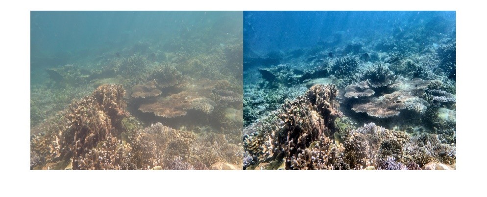
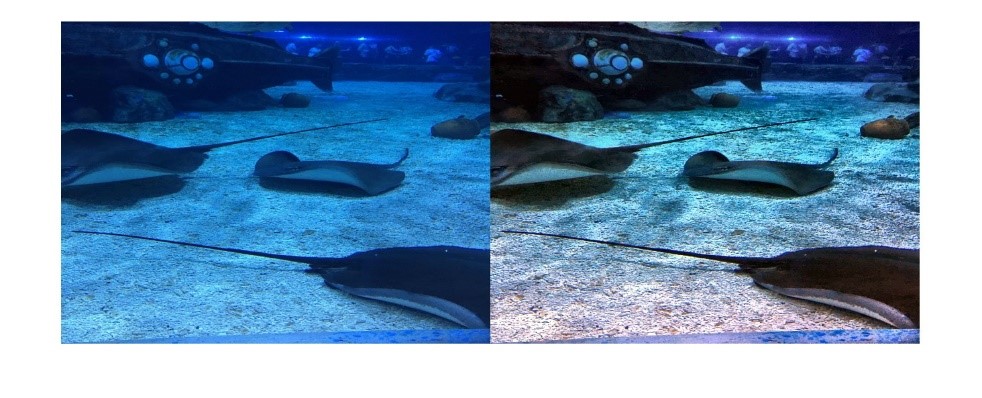
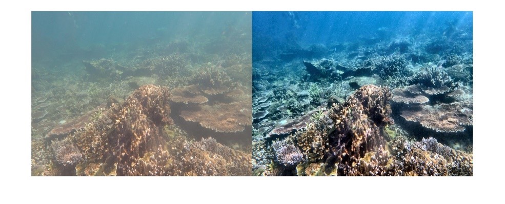
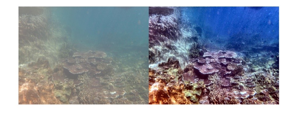
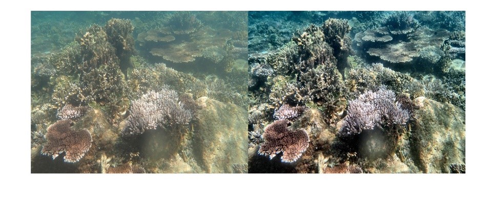
The fusion technique that is used to improve underwater images can be applied in a variety of contexts. Most applications implement this fusion procedure as a pre-processing strategy to enhance the quality of underwater images. Two of the applications are mentioned here, and how they are used in real-world.
Fish detection and tracking
There is a lot of software for Android and iOS devices that can help you identify fish. This software can be your tour guide through the world of fish. Many different kinds of people, from anglers to scuba divers, can use these apps for different tasks. These apps have a lot of pictures and specific information about each fish, like how deep you should dive and where you should go to catch the most fish. You’ll be glad to know that there are apps for both iOS and Android that can help you identify a fish right away. A few of these mobile applications are picture fish, FishVerify, Fishidy, FishBrain etc.
Coral-reef monitoring
Coral reefs keep beaches safe from storms and erosion, create jobs for locals, and give people a place to play. They can also be used to make new foods and medicines. Reefs provide food, income, and shelter for more than 500 million people. Local businesses make hundreds of millions of dollars from people who fish, dive, and snorkel on and near reefs. It is thought that the net economic value of the world’s coral reefs is close to tens of billions of dollars. Underwater Coral Reef is a beautiful, easy-to-use mobile application that lets you customise your device. Underwater Coral Reef is compatible with almost all devices, doesn’t need to be connected to the Internet all the time, uses little battery, and has simple settings for the user interface.
In addition to these applications, the image enhancement strategy’s fusion procedure is used in sea cucumber identification, pipeline monitoring, and other underwater object detection and identification applications.
Product packaging covers are printed with branding and marketing information (refer to Figure 1). A specialised large-scale printing system prints on the packaging material rolls at high speed, which run several meters in length. Any improper setup, a minor misalignment, or the printing process noise itself can introduce defects while printing. These defects have no defined shape or form and can be anything from lines to small color splashes to CMY colour channel misalignments, etc. A defect can be defined as any difference between the intended printing and the actual printing, excluding the process noise (process noise is a slight deviation introduced in printing as the sheet stretches and flaps because of high-speed sheet rollers). Refer to Figure 2 for some examples of printing defects.

These defects can greatly affect the product brand value if it goes undetected and lands at the end consumer’s hand. Hence, early detection of defects is crucial. As the printing happens at high speed, manual inspection gets challenging in spotting defects. Thus the need of an auto-inspection system becomes very important for such use cases.
Problem Statement
The printing speed is somewhere between 2-5 meters per second, which results in a frame rate of 10-20 frames per second. This rate is very high for a human to spot small defects which spread over a few pixels, that too from an image frame of 3000 x 5000 pixels resolution. Hence auto detection is the only way which can bring value to quality assurance. Thus the above requirements can be mapped into following problem statement:
“Using the reference frame (or image), detect any deviations present in the test frame (or image), excluding minor deviations introduced by printing process noise. Processing time should be atleast 100 miliseconds per test frame”

Challenges
- Small Defect Footprint: The defect footprint is tiny compared to the image frame. For example, the defect line width can be as small as 2 pixels whereas image frame is of high resolution i.e. 3000 x 5000 pixels.
- Processing time vs High Resolution Input Frame: The processing time requirement is sub-100 milliseconds to process a frame of 3000 x 5000 resolution. Down-scaling the frame resolution in order to reduce the processing time can make smaller defects to go unnoticed.
- Process Noise: Although process noise is acceptable, it introduces visual variations w.r.t reference frame which makes pixel-to-pixel comparison futile (even with image registration techniques, see Image Registration Approach).
Approach
During the project course following approaches were tried out. We began with Image Registration techniques, followed by deep learning models. The below sections describe this journey and our observations.
Deep Learning using CNN
CNNs have proven to identify patterns in images by auto learning the necessary feature extraction filters (spread over several hidden layers). Also the CNN computations are optimized for GPUs, a low processing time can be expected. Convolution operations are performed on small image patches, whose size is defined by the convolution kernel width. Since these operations are independent, huge speedup is obtained using GPUs. We used Tensorflow, a deep learning framework which makes use of optimized GPU operations under the hood.
Since GPU RAM determines the input size (and output size) that can be processed in one forward pass (the flow of an image through the different layers of a CNN), it was required that we split the high resolution test frame (and hence the reference frame) into small tiles of 256×256 resolution each.
Siamese Network
- Siamese CNN models are a preferred choice when it comes to image comparison. In our case, we need to compare the test frame with the reference frame and identify any defects. Therefore, the Siamese network was our first choice when it comes to CNN.

Image-Siamese Network for defect identification
- We trained a Siamese network following a Tensorflow-Keras tutorial here. To train a siamese network, a dataset must be prepared in triplet form consisting of an Anchor, a Positive example, and a Negative example.
- Where Anchor is the reference image.
- Positive sample is a test sample which contains the print defect and process noise.
- Negative sample is a test sample which has no defect, but just the process noise.
- The dataset creation process is shown below:
- Random images from the internet were collected.
- For the Anchor sample, crops or tiles of shape 256×256 were randomly sampled from the collected images.
- For the negative sample, artificial noise was introduced to the anchor sample. Random rotation (-/+ 1 degree) and random translation (-/+ 6 pixels) were added to the anchor images to obtain the negative sample.
- For the positive sample, random colored lines and splashes were added to represent defect lines in the negative sample.

- It was observed during the training process that the model could not converge beyond a specific loss. This observation holds true even for different CNN backbones and varying hyperparameters.

-
- We hypothesize two reasons that might be playing against model learning:
- Small Defect Signature: Although the Siamese network has been proven effective in obtaining similarity between two images, in our case, the Anchor and Positive images are already visually very similar, apart from a minor defect signature.
- Process Noise Overshadowing Defect: As the test images undergo non-rigid deformation due to process noise, and as we instruct the model to accept the process noise through Anchor and Negative samples, the visual variations of process noise must be overshadowing the visual variations of defects.
- We further hypothesize that because of the above two reasons, the image encoding/features outputted by the Siamese network fails to capture the defect signature effectively, especially for small lines and colour splashes which are a few pixels wide.
Binary Classifier With 6-Channel Input Image
- As the Siamese network failed to learn the defect encodings effectively, we felt a need to extract effective features at the very beginning of the network from the overlap of reference and test image (just like a person would do to spot the difference)
- Overlapping can be achieved by concatenating the test and reference images along the channel axis, forming a 6-channel image that will be an input to the CNN.
- A binary classifier CNN (with sigmoid as the last activation layer) will produce “True” for the input Anchor-Positive pair and “False” for the input Anchor-Negative pair. A pair is now a 6-channel image obtained as stated above.
- We used EfficientNetB0 from Tensorflow as the base network and used the following parameters while instantiating the model:
- input_shape = (None, 256, 256, 6)
- classes = 1
- classifier_activation = “sigmoid”
- This new scheme helped achieve model convergence and 98% accuracy on the validation dataset.
- We hypothesize two reasons that might be playing against model learning:

New scheme to compare tiles for defect detection, where filters in early layers learn to ignore differences due to process noise and focuses on actual defects
-
-
Optimization for Speed
The printing defect detection required a processing rate of 10-20 frames a second, where each frame is a “high resolution” image of 3000×5000 pixels resolution at minimum. Here “high resolution” signifies that input image dimension is high w.r.t conventional CNN applications where input image resolution is usually below 1024 x 1024 pixels. To obtain the desired processing rate of at least 10-20 fps, the following optimization options were possible:
GPU-based Post-Processing Operations
The post-processing operation involved the following operations:
- Tile Formation and Extraction: tile formation and extraction must be performed for reference and test frames, where each tile is 256×256 crop.
- Tile Concatenation: Tile from reference and test frames will be concatenated based on their respective positions along the channel axis.
- Batch Formation of Concatenated Tiles: Batch processing of 6-Channel image (obtained by respective tile concatenation) is faster than processing of single 6-Channel image.
Above operations were initially implemented in OpenCV and were executed on CPU, a GPU equivalent will significantly speed up the operation. This transfer of execution to GPU can be achieved by either writing a customized CUDA kernel OR using Tensorflow Graph as explained below.
Use Of TensorFlow Graph Execution Instead Of Eager Execution
Tensorflow by default makes use of eager flow, where Python Interpreter orchestrates the execution and hence some latency is introduced along the way. Graph execution is a way by which a computation graph is created describing the user’s operation, which can be executed faster without involving python interpreter. More details can be found in the introduction on TF Graph blog. Below is the implementation of tensorflow:
Summary
Using the optimization techniques mentioned above and GPUs such as GTX1660ti and RTX A4000, we achieved a performance of less than one second (approximately 0.9 seconds) per frame. This is a significant improvement from the starting point of over 20 seconds of execution time per frame. For further improvement below are planned methods for speed optimizations.
Other Planned Methods for Speed Optimization
Our objective is to take execution speed down to 100 milliseconds per frame, and towards that goal below are techniques we want to make use of:
- Use of CUDA Pinned Memory Transfer: for test images, Pinned memory will be used to transfer subsequent test frames to GPU. Pinned memory is a type of memory that remains in a fixed location in the system’s physical memory and is not subject to virtual memory paging. This arrangement has several advantages over regular pageable memory, like faster transfer of memory, improved concurrency, and reduced CPU overhead.
- Use TensorFlowRT: TensorFlow RT is optimized for fast inference performance and is designed to take full advantage of the hardware acceleration available on GPU. The optimization primarily involves lowering the precision from default FP32 to FP16 or even INT8, which results in faster computation and a lower model footprint.
- Use Of Multi-GPU configuration: Although having a multi-GPU system is costlier, it improves speed. The high-resolution master and test frames can be split into parts, and the corresponding defect detection can be spread over multiple GPUs to further speed up time.
-